


.jpg)
Lesson on Arithmetic and Logical unit with circuit diagram
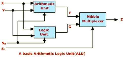
Arithmatic Unit:
- ALU is a single circuit, and this performs arithmetic and logical operations
- This is core of any processor
- A typical ALU will have two input ports and a result port. It will also have a control input telling it which operation
- To perform arithmetic and logical operations necessary operands are transferred from memory location to ALU where it is stored in the temporary registers
- It also has necessary hard ware to perform operations on signed, unsigned integers, floating point numbers, BCD numbers etc.
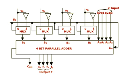
Let us consider the Circuit of Arithmetic Unit given below
- It has 4 bit parallel adder
- X and Y are the two input operands each of 4 bit
- There are 4 one of two multiplexers associated with the y operand of the parallel adder
- The multiplexer selects either y or Y' depending on the selection
- line S0 which is also carry in, input to the adder
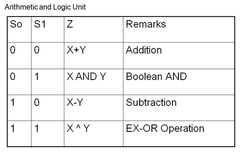
- If S0=0 Output is F=X+Y
- If S0=1 Output is F=x+y'+1 where y'+1 is 2' complement of y, so the output is F=X-Y
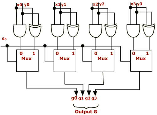
Consider a simple logic unit given below which can perform two logic operations AND and EXCLUSIVE OR. The multiplexer selects either of the operations depending on the selection line S0.
- If S0=0 out put is G=X AND Y
- If S0=1 out put is G= X ^ Y (Exclusive OR)
- Some additional hard ware is also added to perform other Boolean operations
Example:
X'=X ^ 1
X^Y^Y^XY=X OR Y
Lesson on Cache Memory and Memory Access modes << Previous
Next>> Control Unit
Support us generously: contact@lessons2all.com
Our aim is to provide information to the knowledge seekers.