Performing an Arithmetic or Logic Operation
- The ALU perform arithmetic and logic operations.
- It does not have any internal storage. So to perform an operation two operands should be brought at two inputs of the ALU
- Registers Y and Z are used for this purpose
- Register Y is used to hold one of the operands while other is gated into the bus.
- The result is stored in the Z register.
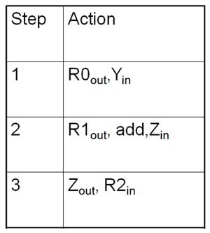
Consider an add operation to add content register R0 and register R1 and store the result in register R2. Sequence of operations is as follows, Register Y or Z are used to hold one of two operands.
Step1: O/P gate of R0 and gate of Yin are enabled, causing the content of R0 to be transferred to Y. Now the content of Y is available at the input A
Step 2: The Contents of R1 are gated onto the bus because O/P of R1 is enabled so it is available to B. Add line is set to 1, to add the contents of A and B. Input gate of Z is enabled and sum loaded in Z
Step 3: Contents of Z transferred to destination register R2 because o/p gate of Z and i/p gate of R2 are enabled
Table 1
Timing of Data Transfer between Registers
Consider the addition operation After the signal R1out is set to 1 following delays will be observed
- A finite delay is encountered for the gate to open
- For the data to travel along the bus to the input of ALU
- ALU adder circuits
- For the result to be properly stored in register Z, data must be maintained on the bus for an additional period of time equal to the setup and hold times for this register
The sum of delays times is the minimum duration of the signal R1out
TWO BUS STRUCTURE
- Consists of Two Buses Bus A and Bus B
- In this all the register outputs are connected to bus A and all the register inputs are connected to bus B.
- Two Buses are electrically connected together by the bus tie G.
- When G is enabled, it transfers data on bus A to bus B and when it is disabled two buses are electrically disconnected.
- The temporary register Z is not required in this organization because when the bus tie G is disabled, the output of ALU can be transferred directly to the destination register
Example
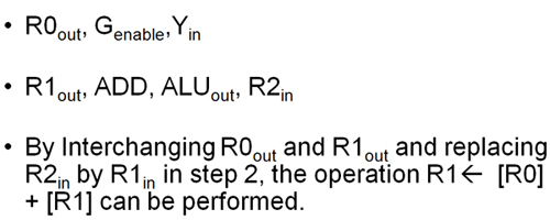
- Add the content stored in the register R0 with the content stored in the register R1 and store the result in register R2. The same previous example let us see how it differs here

Register Transfers << Previous
Next >> THREE BUS STRUCTURE
Support us generously: contact@lessons2all.com
Our aim is to provide information to the knowledge seekers.


.jpg)