Branching
- Branching is achieved by replacing the current contents of the PC by the branch address.
- Branch address is obtained by adding an offset X given in the address field of branch instruction, to the current value of PC
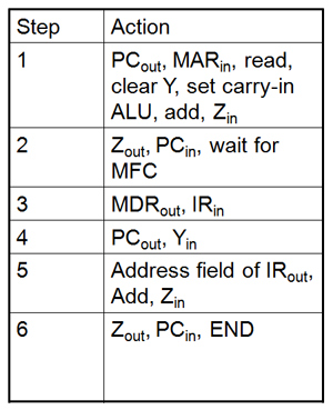
Table 3

The table shows the control sequence for an unconditional branch using single bus organization
Note: Since Steps 1 to 3 are already discussed only Step 4 to Step 6 are discussed below, this is with reference to unconditional branch instruction of table3.
Step 4: IR will be decoded in the beginning. To execute branch instruction, the contents of PC are transferred to register Y
Step 5: The offset X is gated onto the bus, and the addition operation is performed which forms the branch address
Step 6: The branch address is loaded into the PC. Here PC is incremented during the fetch phase, before knowing the type of instruction being executed. At the same time the offset X is added to the contents of the PC. Hence offset X is the difference between the branch address and the address immediately following the branch instruction. For example if the branch instruction is at location 3000 and it is required to branch to location 3050, the value of the X must be 49
Consider the conditional branching. In this case the status of the condition codes must be checked before loading a new value into the PC. For example, for a conditional branch instruction, step 4 is replaced with
PCout, Yin, if N bit is zero then End [No need to calculate the new PC contents]
As earlier, the contents of the PC are copied into register Y, just in case they will be needed to compute the branch operation. Meanwhile the N bit is checked. If it is zero the execution is terminated using End signal. If N is 1, remaining steps are executed.
THREE BUS STRUCTURE << Previous
Next >> Sequencing of Control Signals
Support us generously: contact@lessons2all.com
Our aim is to provide information to the knowledge seekers.


.jpg)